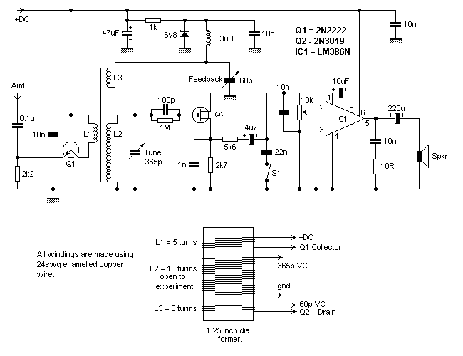

This simple design is based on a 'Regenerative' tuned radio freqeuncy-type receiver. The antenna signal enters RF amplifier Q1 and coupled via LI. This induces a small signal into winding L2 which is brought to resonant frequency by the 365pF variable capacitor.
The signal is then rectified and amplified by FET Q2. A small portion of this signal is taken from the Drain of Q2 and fed back to the signal input via L3. In thoery this greatly increase the 'Q' of the circuit and also the selectivity. The 60pF variable capacitor adjusts the amount of feedback in the circuit. The supply for this part of the circuit is taken via the 6V8 zener diode for better stability.
After Q2 the rectified Af signal is amplified by IC1 - a small audio power amplifier which is sufficient to drive a small loudspeaker or headphones. Switch S1 connects the 22nF capacitor across the audio input and is just a very simple low-pass filter.
For more details of wire thicknesses, see Wire Guages on the Index page.
Best Regards... Pete
http://www.keirle.fsnet.co.uk